If you do
NOT see the Table of Contents frame to the left of this page, then
Click here to open 'USArmyGermany'
frameset |
Army
Air Defense in the European Theater
Fire Control Systems
Looking for more information from military/civilian
personnel assigned to or associated with the U.S. Army
in Germany from 1945 to 1989. If you have any
stories or thoughts on the subject, please contact me . .
|
|
|
|
|
|
| M33 -- Antiaircraft Fire Control System |
| |
| 1950s |
| (Source: TM 9-6092-1-1, Antiaircraft Fire Control System M33C and M33D Operation, June 1956) |
Section II. DESCRIPTION OF THE ANTIAIRCRAFT FIRE CONTROL SYSTEM M33
4. General
 a. This section contains a general description of the antiaircraft fire control system M33 (AA FCS M33). It is intended to acquaint operating personnel with the location and function of the components involved in the operation of the system. a. This section contains a general description of the antiaircraft fire control system M33 (AA FCS M33). It is intended to acquaint operating personnel with the location and function of the components involved in the operation of the system.
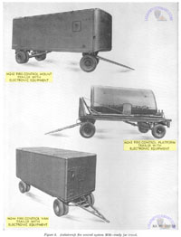
b. The principal components of the AA FCS M33 are the acquisition antenna assembly, tracking antenna, radar cabinet, computer, tactical-control console, and the tracking console. This system, with its equipment, is normally issued to the troops and transported in three trailers (figs. 1 and 2) as described in (1) through (4) below.
(1) All of the principal components, except for the acquisition antenna assembly, are permanently installed in, or mounted on, the M242 fire-control mount trailer.
(2) The acquisition antenna is transported on the M243 fire-control platform trailer. When the antenna is emplaced, the trailer is packed off site.
(3) All of the spare parts, tools, and some of the equipment are carried in the M244 firecontrol van trailer. This trailer has a working area for the performance of authorized repairs.
(4) The 11 reels of cable, used to interconnect various portions of the AA FCS M33, are transported by the using organization in general cargo prime movers on system serial numbers 132 through 682. On system serial numbers 682 and higher, an M36C truck replaces the M243 fire-control platform trailer. The M36C truck is used to transport the acquisition antenna and the antenna erecting equipment. In addition, storage space is provided on this truck for transporting the 11 reels of cable used to interconnect the various portions of the AA FCS M33. Descriptive information and instructions covering operation and organizational maintenance of the M36C truck will be provided at a later date.
c. These trailers are capable of traversing the same terrain as the antiaircraft guns; on long moves, the trailers may be transported by rail, ship, or aircraft. Instructions covering operation and organizational maintenance of the trailers will be furnished in a separate manual. However, because of the operational usage of the trailers with the basic fire control systems, certain operational procedures are included in this manual. |
 |
|
d. The designations M242, M243, and M244 apply to the unloaded trailers. Different designations are used to identify the trailers with electronic equipment as outlined in (1) through (3) below.
(1) Fire-control-system trailer designates
M242 trailer with electronic equipment.
(2) Acquisition-antenna trailer designates
M243 trailer with electronic equipment.
(3) Maintenance-and-spares trailer designates
M244 trailer with electronic equipment.
|
|
|
| e. The AA FCS M33 is a mobile, integrated, electromechanical fire control system. It is capable of locating and displaying high-speed targets within the defense area, and supplying firing data to direct accurately the fire of 90-mm or 120-mm antiaircraft guns. To accomplish its mission, the AA FCS M33 requires from outside sources only primary power, early warning information, and meteorological data. Provision for installing identification friend or foe equipment (IFF) is incorporated in the system. Included in the AA FCS M33 are an acquisition radar, tracking radar, and a computer. Information from the acquisition and tracking radars, required to direct operation of the antiaircraft battery, is presented at a tactical-control console which is included with the system. The acquisition radar continuously searches the defense area and presents target position information from all targets in this area. With the use of the associated IFF equipment, hostile targets may be determined. From the target display of the acquisition radar, any target may be selected and transferred to the tracking radar. While the acquisition radar continues to search the defense area, the tracking radar tracks the selected target and provides accurate present position information to the computer. On the basis of the present position information received from the tracking radar and the meteorological data received from outside sources, the computer automatically and continuously determines the firing data which is used to direct the guns and set projectile fuzes of the associated antiaircraft guns. |
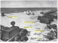
1. M33 -- emplaced
|
2. M33 -- ready to travel
|
3. M242 trailer -- plan view |
|
|
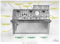
5. Fire-Control-System Trailer
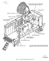
The fire-control-system trailer (fig. 1), when emplaced, serves as the operational center for the AA FCS M33. It includes the M242 fire-control mount trailer (fig. 3), which houses the other components of the fire-control-system trailer and the operating personnel. Inside the trailer, on the roadside of the trailer, are the computer and the tactical-control console. On the curbside of the trailer are the switchboard cabinet and the early-warning plotting board T17. Forward of the tactical-control console is the tracking console. At the front of the trailer are the radar cabinet and the heater cabinet. In some trailers, the heater cabinet has been replaced with a vehicle-mounting duct-type heater. Arranged at the various operator positions are chairs for the operators. Mounted on top of the trailer is the tracking antenna which includes the upper-section periscope. Portions of the tracking antenna, including the lower-section periscope, project into the interior of the trailer over the tracking console. Built into the exterior curbside wall of the trailer is the data junction plate which contains connectors for cables to the gun battery and a terminal strip for telephone connections. At the front of the trailer is the acquisition and power cable panel for cable connections to the acquisition antenna and the external power source. Air ports or vents for personnel and equipment ventilation are located in the front, rear, and roadside of the trailer.
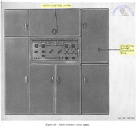
6. M242 Fire-Control Mount Trailer
The M242 fire-control mount trailer (fig. 3) is designed to house the complex electronic equipment of the AA FCS M33 and to provide operating conditions for personnel which insure maximum efficiency and alertness. In addition to protecting the electronic equipment from the weather, the trailer permits operation and adjustments to the equipment when blackout restrictions are in force. The trailer is a full trailer, rather than a semi-trailer, to permit its being hauled over difficult terrain by a towing vehicle. Through use of special design features and light materials, the weight of the equipment is kept at a minimum value. The trailer can be sealed from light, dust, and water. With the door and all covers closed and secured, the fully loaded trailer can be floated upright without damage to the equipment. Jacks are built in at the four corners of the trailer to permit leveling, so that data will be accurately referenced to the horizontal plane. Spirit levels are used in leveling the trailer.
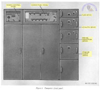
7. Computer
a. The computer (fig. 3), when supplied with target position data by the tracking radar, determines firing azimuth and firing elevation data in mils and fuze data in fuze numbers. This data is supplied to the associated gun battery as electrical values.
b. The computer (fig. 5) includes the power-control panel, correction panel, fuze servo, azimuth servo, firing-elevation servo, and time-of-flight servo in addition to electronic components. Controls for energizing the computer are mounted on the power-control panel. The correction panel contains controls for setting in battery parallax, ballistic, and meteorological data, and for displaying the data. The correction panel also contains controls for use in checking computer performance. The fuze servo contains controls and dials for correcting and indicating fuze data being furnished to the guns. Controls and dials for correcting and indicating firing azimuth data being furnished to the guns, and controls for setting in wind azimuth data are mounted on the front of the azimuth servo. The firing-elevation servo contains controls and dials for correcting and indicating the firing elevation data being furnished to the guns. Time of flight of the projectile to the predicted target position may be read on the dial of the time-of-flight servo.
c. The computer has three types of prediction: linear, tangential, and quadratic. Linear prediction is used when the target is flying a straight non-accelerating course, tangential prediction when the target is flying a slightly curved or slightly accelerated course, and quadratic prediction when the target is flying a curved course or is accelerating rapidly. Selection of the type of prediction is made by controls on the target-rate indicator which is on the tactical-control console. From the information indicated on the dials of the target-rate indicator and the plotting boards, the type of prediction required for the computer may be determined.
d. The computer is designed so that those parts depending on the ballistics of the gun and ammunition are replaceable. This makes it possible to use the system with 90-mm guns (M33C) and with 120-mm guns (M33D) by changing certain subassemblies of the computer.
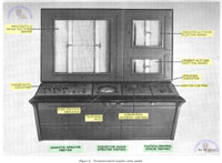
8. Tactical-Control Console
a. The tactical-control console (fig. 3) contains controls and provides a display of information which permit intelligent direction of the firing of the battery. At the tactical-control console are positions for the tactical-control officer, the acquisition-radar operator, and the computer operator.
b. Mounted on the sloping panel of the console (fig. 6) at the tactical-control officer's position is the monitor-control, which provides a signaling system for directing the operation of the AA FCS M33 and the guns of the battery. This signaling system provides a more rapid and dependable control of the battery than could be obtained by the use of the telephone alone. Through the use of colored signal lights, the tactical-control officer can see at a glance the state of readiness of the guns and all parts of the fire control system. By means of controls, he can challenge a target and indicate to the members of the battery whether the challenged target is hostile or friendly. Also, by controls operating signal lights and horn, he gives the order to commence fire or to cease fire. Circuits are arranged so the commence fire signal cannot be given until certain parts of the battery are ready.
c. From the tactical-control officer's position, the control officer can see the early-warning plotting board and observe the target through the periscope of the tracking antenna (fig. 3).
d. At the acquisition-radar operator's position are a 10-inch plan-position indicator (PPI), an "expanded B" precision indicator, and the acquisition-antenna control. The indicators are visible also to the tactical-control officer.
e. The PPI displays all targets within 6,400 mils of azimuth and 60,000 or 120,000 yards of range. Special moving-target-indicator circuits eliminate the presentation of nearby stationary targets, permitting only moving targets to be displayed. The PPI displays an acquisition range mark and a steerable azimuth line. These marks are used for designating targets in range and azimuth. Also appearing on the PPI is an electronic cross which indicates the range and azimuth setting of the tracking radar. This electronic cross enables the tactical-control officer to note the location of the target being engaged.
f. The precision indicator displays an enlarged portion of the PPI presentation. It is centered about either the electronic cross of the tracking radar or the azimuth line and range circle of the acquisition radar.
g. The acquisition-antenna control permits positioning of the steerable azimuth line and acquisition range mark to designate a target. The acquisition-antenna control may be used to follow and point out the next target to be engaged, while the tracking radar is tracking the target previously designated.
h. The target-rate indicator, located at the computer operator's position, provides meters which indicate the target's tactics and serve as the basis for determining the computer type of prediction. Controls for selecting the computer type of prediction and the plotting boards mode of operation are located on the target-rate indicator panel. Also located on this panel are signal lights and controls for regulating illumination of the tactical-control console, plotting boards, and computer servos.
i. A telephone jack is secured to the underside of the shelf of the tactical-control console.
j. Mounted above the sloping panel of the tactical-control console are three automatic plotting boards which accurately plot the course and tactics of the target, and the location of future target positions with respect to any areas in which firing may be restricted. In addition, the plotting boards may be used to check the performance of the tracking radar and computer. These boards are the horizontal-range, present-altitude, and predicted-altitude plotting boards.
k. The horizontal-range plotting board plots a continuous record in the horizontal plane of both the present position and predicted position of the target. The plotting board also plots fire, cease fire, and 20-second timing marks to give a permanent plot of a target engagement for future study and evaluation. A series of concentric range circles and radial azimuth lines are engraved in the transparent plastic backboard and appear behind transparent plotting paper. This provides a means of reference, since the origin of these coordinates corresponds to the gun directing point. Variable intensity lights behind the plastic backboard illuminate the plot. The 1:100,000 scale allows the use of standard military maps to make overlays to be used behind the plot. The overlays show such things as the locations of the objectives being defended and the restricted areas into which shells should not be fired.
l. The present-altitude plotting board plots the present altitude of the target against the present ground range of the target. The plotting board also plots fire, cease fire, and 20-second timing marks. A series of slant range circles in 5,000-yard steps are inscribed on the plastic backboard, together with horizontal altitude lines in 2,000-yard steps. The origin of these coordinates corresponds to the tracking antenna and is located near the lower left corner of the board.
m. The predicted-altitude plotting board plots the predicted altitude of the target against the predicted ground range of the target. The plotting board also plots fire, cease fire, and 20-second timing marks to give a permanent plot of a target engagement for future study and reference. A series of gun trajectory curves in steps of 20-mil elevation and time-offlight arcs in 5-second steps are inscribed on the plastic backboard. Because gun trajectories and time of flight are a function of the particular type of gun, the plastic backboard used for the M33C differs from that used for the M33D. The origin of these coordinates corresponds to the gun directing point and is located near the lower left corner of the board.
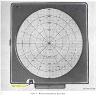
9. Early-Warning Plotting Board T17
The early-warning plotting board T17 (fig. 3) is a manually operated plotting board upon which plotted information received by telephone from the early-warning radar net is recorded. Target data up to a maximum of 250,000 yards may be plotted on the plastic board (fig. 7) with a wax pencil. A series of concentric range circles and radial azimuth lines, engraved in the transparent plastic plotting board, provide a means whereby any approaching targets may be plotted fairly accurately. A telephone jack is mounted at the bottom of the board. |
5. Computer
|
6. Tactical-control console
|
7. Early-warning plotting board |
|
|
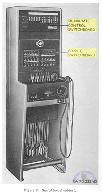
10. Swtichboard Cabinet
a. The switchboard cabinet (figs. 3 and 8) contains switchboards BD-91-C and SB-100/MTC. It provides line and hot-loop communications within the battery, lines to units outside the battery, and trunk lines to early warning nets or higher echelons through a dial system.
b. The BD-91-C switchboard contains 20 typical field line circuits, four trunk line circuits, a four-jack conference circuit, a night-alarm buzzer circuit, operator's telephone jack, and an automatic dial for use with trunk circuits. The 20 field line circuits make use of the equivalent of magneto ringing, portable, field telephone sets. Seven line circuits and the four trunk line circuits are connected directly to their assigned points. The assigned points are the tactical-control-console telephone jack (fig. 6), the early-warning-plotting-board telephone jack (fig. 7), and the data junction plate (fig. 3). The other 13 line circuits are controlled by the SB-100/MTC switchboard.
c. The SB-100/MTC switchboard contains a battery commander's telephone jack, a LOOP 1-LOOP 2 switch, a RELEASE-TEST switch, and slide switches for selecting individual lines to be transferred into one of two loop circuits. When the BATTERY ALERT switch is depressed, the individual field lines either remain connected directly to the BD-91-C switchboard or are interconnected into one of two loop circuits, depending on the position of the pertinent slide switch or switches. The telephone lines are usually connected into the loop circuits as outlined in (1) through (4) below.
(1) Telephone lines within the firing battery proper are usually connected into the loop 1 circuit. The telephone jacks for these lines are located at the generator, acquisition RF coupler (fig. 17), guns, tracking console (fig. 9), and M242 fire-control-mount-trailer roof (fig. 65). In addition, two square lines are provided for use if necessary.
(2) The four telephone lines in the perimeter defense (machineguns No. 1, No. 2, No. 3, and No. 4) are permanently connected into the loop 2 circuit and no slide switches are provided for these lines.
(3) The telephone line for the battery executive may be connected into the loop 1 circuit, loop 2 circuit, or the BD-91-C switchboard, by adjusting the pertinent slide switches to the desired position. Also available are two spare telephone lines which can be connected in a similar manner.
(4) In addition, the battery commander may use the jack on the SB-100/MTC switchboard and converse with either of these loops by operating the nearby LOOP 1-LOOP 2 switch. The same applies to the telephone jack at the tactical control console (fig. 6) where there is a similar LOOP 1-LOOP 2 switch.
d. When deemed necessary, commercial telephone lines have been connected into the M242 trailer. The commercial telephone cable containing the individual lines may be run directly from outside telephone facilities into the trailer through a hole drilled in the data junction plate or the cable may be connected to a connector installed at the data junction plate. The commercial telephone lines are terminated at three jacks which are installed at the early-warning plotting board, tracking console, and tactical-control console. These commercial telephone circuits operate independently of the telephone switchboard.
e. Additional information on switchboard BD91-C and SB-100/MTC is contained in TM 11-4313 and TM 11-2133, respectively.
11. Tracking Console
a. The tracking console (figs. 3 and 9) provides indicators and controls for observing and tracking the target designated by the tactical-control officer. At the tracking console are positions for the elevation operator, azimuth operator, and range operator.
b. The tracking console contains the front panel assemblies described in (1) through (9) below.
(1) Three tracking indicators which display
tracking marks and target video.
(2) A PPI which is identical to and displays the same information as the PPI on the tactical-control console.
(3) A precision indicator which is identical to and displays the same information as the precision indicator on the tactical-control console.
(4) A trial-fire indicator which provides means for observing range deviations during trial-fire and velocity-fire tests.
(5) A tracking-receiver control which contains controls and indicators used in making remote adjustments to the tracking radar receiver.
(6) An acquisition-receiver control which contains controls and indicators used in making remote adjustments to the acquisition radar receiver.
(7) An indicator high-voltage power supply with mounted signal indicator lights and controls which are a part of the signaling system of the tactical-control console. Also mounted on the indicator high-voltage power supply are controls for varying the brightness of the signal indicator lights, dial lights, and the ceiling lights near the tracking console.
(8) A tracking-console control drawer which contains controls used in tracking a target in manual or aided operation. The control drawer also contains controls for selecting the mode of operation and other miscellaneous operating controls.
(9) A telephone jack which is attached to the
underside of the tracking console shelf.
12. Radar Cabinet
The radar cabinet (fig. 3) houses many of the assemblies of the acquisition and tracking radars. Mounted in the center of the cabinet is the power-control panel (fig. 10). On the panel are controls for energizing and making operating adjustments to the radars. In the upper right panel is the tracking-range-computer dial on which the setting of the tracking range computer may be read in yards.
13. Heater Cabinet
(not transcribed)
14. Vehicle-Mounting Duct-Type Heater
(not transcribed) |
8. Switchboard cabinet
|
9. Tracking console
|
10. Radar cabinet |
|
|
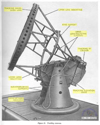
15. Tracking Antenna
a The tracking antenna (fig. 3) radiates a sharply focused pencil beam in a conical path. It receives pulses reflected from any target upon which it may be directed. The antenna is capable of moving through 6,400 mils of azimuth and from -180 mils to + 1,600 mils of elevation.
b. When emplaced, a portion of the tracking antenna (fig. 13) is mounted on the turntable of the azimuth drive on top of the M242 trailer. The remainder of the antenna is built into the trailer roof above the tracking console (fig. 14). The portion of the tracking antenna mounted on top of the trailer consists of the tracking RF coupler, tracking elevation drive, elevation-drive supports, tracking wave-guide lens, upper-section periscope, and the tracking-lens mounting, which consists of the upper lens mounting, lower lens mounting, upper hensmounting supports, and ring support.
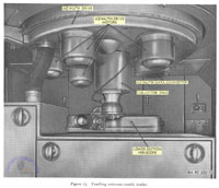
c. The tracking RF coupler contains electronic assemblies associated with the tracking radar. The elevation drive moves the antenna in elevation. The elevation-drive supports, mounted on the azimuth drive turntable, hold the assemblies mounted on them in place in azimuth while allowing motion in elevation. The wave-guide lens, supported by the lens mounting, focuses the transmitted pulses and received pulses. The upper-section periscope with the lower-section periscope (fig. 14) inside the trailer make up the periscope assembly which provides optical tracking. Also inside the trailer mounted in the roof are the azimuth drive, azimuth data converter, and collector ring. The azimuth drive moves the antenna in azimuth. The azimuth data converter supplies azimuth data to the computer, and collector rings provide electrical connections between the rotating and stationary portions of the antenna.
d. When ready for travel, the components mounted on the trailer roof are stored behind the clamshell doors at the front of the trailer (fig. 15) and inside the trailer. Those components of the tracking antenna mounted in the trailer roof are not removed for travel.
16. Acquisition Antenna Assembly
a. When emplaced, the acquisition antenna assembly (fig. 1) is located within 250 yards of the fire-control-system trailer. The acquisition antenna assembly (fig. 17) includes the antenna, acquisition-antenna drive, acquisition RF coupler, acquisition modulator, acquisition-antenna mounting legs and leg braces, acquisition-antenna leveling jacks, acquisition-antenna orientation test set, and interconnecting cables.
b. The antenna focuses and radiates transmitted pulses in either a pencil-shaped beam or a cosecant-squared beam. It normally rotates continuously through 6,400 mils of azimuth. The antenna also picks up the signals reflected by targets and directs them to the acquisition RF coupler.
c. The acquisition-antenna drive contains a motor which rotates the antenna at speeds of 10, 20, or 30 revolutions per minute. It also provides a rotary connection between the rotating antenna and the stationary RF coupler. Controls for orienting the acquisition antenna are provided inside the acquisition orient compartment (fig. 17). The acquisition RIF coupler and acquisition modulator contain electronic assemblies associated with the acquisition radar. The antenna mounting legs, leg braces, and jacks support the emplaced acquisition antenna assembly.
d. The acquisition-antenna orientation test set includes two spirit levels for leveling the acquisition antenna assembly and a peep sight for orienting the antenna.
e. When ready for travel, the antenna drive, RF coupler, modulator, and mounting legs are carried inside the M244 fire-control van trailer. The antenna and erecting equipment are carried on the M243 fire-control platform trailer (fig. 2).
17. Acquisition-Antenna Trailer
The acquisition-antenna trailer (fig. 1), which includes the M243 fire-control platform trailer, provides means for transporting the antenna of the acquisition antenna assembly and equipment used in erecting the acquisition antenna assembly.
18. Maintenance-and-Spares Trailer
a. When emplaced, the maintenance-and-spares trailer (fig. 1) serves as a maintenance workshop. The trailer (fig. 18) includes the M244 fire-control van trailer, a heating-and-ventilating cabinet, a service bench, and cabinets which provide storage for organizational tools, equipment, and spare parts. The trailer contains ventilation openings for personnel, a lighting system, and blackout curtains.
b. During transit, the acquisition-antenna drive, RF coupler, modulator, and mounting legs are carried in the trailer. This trailer can be scaled from light, dust, and water and can be floated upright when all doors and covers are closed and secured. |
13. Tracking antenna |
14. Tracking antenna -- inside trailer |
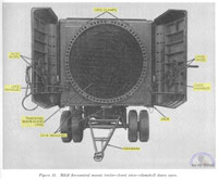
15. M242 trailer -- clamshell doors open |
|
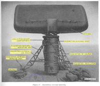
17. Acquisition antenna assembly |
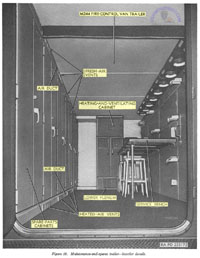
18. M244 trailer -- interior details |
|
|
|
19. Heating-and-Ventilation Cabinet
(not transcribed)
End of Section II
|
 |
|
|
| M33 Integrated Fire Control Repair |
|
| (Source: STARS & STRIPES, December 3, 1954) |
A 7½-month project to equip all 90-mm antiaircraft battalions in the 34th AAA Brigade with the new M33 radar fire control system has recently been completed at the Mainz Ordnance Depot.
The last unit to be equipped was the 95th AAA Battalion. (The project started in May with the delivery of the first fire control units to USAREUR.)
The Western Electric electronic fire control unit costs $383,000. Its radar can spot aircraft at a distance greater than 75 miles.
The unit automatically tracks and computes for four guns apiece (= a firing battery). The M33 is comprised of a radar van, a flat bed for its antenna and a shop van for maintenance and supply.
The 90-mm guns of each battalion had to be modified by the ordnance depot for use with the M33.
Prior to the integration with the M33, the 90-mm batteries used two separate pieces of equipment for radar and firing. They were not completely integrated.
CG of the 34th AAA Bde at this time is Brig Gen Frank C. McConnell ; CO of the 95th AAA Bn is Lt Col J. T. Materi.
Mainz Ord Depot CO is Col John W. Cave. |
|
|
| (Source: STARS & STRIPES, January 30, 1957) |
There are three radar repair units in 7th Army that are responsible for maintaining the M33 Anti-aircraft Fire Control System used by the 90mm Gun battalions within the 34th AAA Brigade. These units operate on a geographical basis. The three units are:
150th
Ord Det (IFCR M33) at Wiesbaden
151st
Ord Det (IFCR M33) at Mannheim
152nd Ord Det (IFCR M33) at Kaiserslautern
The S&S article referred to as the source, covers the activities of the 151st at Mannheim.
The 151st Ord Det is located at Sullivan Barracks and is commanded by CWO Richard H. Toothaker. This detachment supports the 95th AAA Bn at Sandhofen and the 552nd AAA Bn in Karlsruhe. (Webmaster Note: I am guessing, but the 150th probably supported the 25th and 63rd AAA Bns; the 152nd would have supported the 40th and 45th AAA Bns.)
Two roving teams (Sandhofen Contact Team and Mannheim Contact Team) each operate a mobile repair van and visit the supported battalions on regular maintenance visits. The teams make on-the-spot inspections and perform preventive maintenance and field changes as well as minor and major repairs. The objective is to avoid having to deadline an M33 for any length of time. Loss of an M33 creates a hole in the AA protection. Each FDC controls a firing battery of four 90mm guns. Temporary loss of the acquisition radar antenna or tracking radar puts the battery out of business until the FDC is back on line. |
|
|
|
| T38 -- Antiaircraft Fire Control System |
| |
| 1950s |
| (Source: TM 9-3026-1, Improved Antiaircraft Fire Control System T38 Operation, December 1955) |
Section I. INTRODUCTION AND DESCRIPTION
1. Scope
a. This volume contains a description of and operating instructions for the improved fire control system T38.
b. This volume is the first of three volumes of instructions on the operation and organizational maintenance of fire control system T38.
(1) Operation -- TM 9-3026-1
(2) When published, TM 9-3026-2 will contain organizational maintenance instructions
(3) Electrical schematic diagrams -- TM 9-3026-3
c. This volume consists of three sections. Section I describes the general characteristics and functioning of the integrated weapon, describes and locates the components of the improved fire control system, and supplies tabulated data on these components. Section II lists the controls and instruments of the fire control system, describes their functions, and furnishes detailed instructions for the operation of the system. Section III contains the boresighting procedure and procedures for testing and adjusting the components of the fire control system.
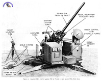
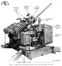
d. The fire control system (figs. I and 2) comprises the following components: radar tracker T9, computer T27E2, periscope T33 (which together form director T41E2), power control T21E1, target selector T1E2, sighting system T34E1, cable system T31E1, and wiring set T5E2. These components are used in conjunction with 75-mm AA gun T83E6 and T83E7 on 75-mm AA gun mount T69 and, with loader rammer T23 and recoil mechanism T47E2 or T47E3 form a completely integrated antiaircraft weapon designated as the "Skysweeper."
e. For the theory of operation of the basic fire control system T38, reference should be made to TM 9-6081-1. For tabulated data on the basic system and on the gun, gun mount, recoil mechanism, and loader rammer, reference should be made to TM 9-361. TM 9-361 also describes maintenance procedures and the uses of special tools and equipment listed in ORD 7 SNL D-48 pertaining to organizational maintenance of these components. For ordnance maintenance of the gun, gun mount, recoil mechanism, and loader rammer, reference should be made to TM 9-3027.
|
1. Improved FCS T38 on 75-mm AA gun mount T69, front view
|
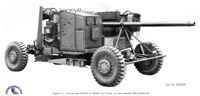
2. Improved FCS T38 on 75-mm AA gun mount T69, rear view
|
3. 75-mm gun T83E6 or T83E7 on 75-mm AA gun mount T69, limbered |
|
|
| |
2. General Description
a. Characteristics.
(1) Consolidation of the components of the fire control system with components of artillery on a single, highly mobile mount is the principal characteristic of this weapon (fig. 3). Such consolidation compactly integrates the weapon both mechanically and functionally. The effectiveness of the weapon is further increased in that the components of the fire control system are permanently matched and complement each other in the solution of the fire control problem.
(2) The weapon is designed primarily for use against low flying, high speed aircraft, has a medium range, and features automatic loading which enables a rate of fire up to 55 rounds per minute. By virtue of its low limit of depression the weapon may also be used against ground targets. Facilities for emergency manual gun laying are also provided.
b. Description.
(1) The weapon (fig. 3) utilizes a mount that is towed by a van-type primer mover on two removable bogie suspensions. The mount consists of a pedestal and a rotatable top carriage. The pedestal incloses the electro-hydraulic emplacing mechanism, and the junction box and collector ring assembly of the wiring set, while the top carriage supports the artillery components and the radar, computer, and power control of the fire control system. These components are electrically interconnected by the armored cabling of the wiring set. The cable system connects the junction box of the wiring set to a power source for providing power for the entire mount. The weapon (fig. 1) fires primarily from an emplaced position but may be fired against ground targets with the aid of the auxiliary sighting system when mounted on the bogie suspensions.
(2) The 75-mm gun (fig. 1) and associated recoil mechanism are supported in the gun cradle which is trunnioned in bearings in the two gun frames centrally located on the top carriage. The automatic loader rammer (figs. 1 and 2) is
fastened to the cradle over the gun breech. The transmission box of the loader rammer permanently supports a transverse mounting bracket, which is part of the sighting system (figs. 1 and 2), to which the telescope brackets containing, respectively, the azimuth and elevation telescopes of the sighting system are secured during emergency gun operation. The gun cradle and the items it supports are the tippable parts of the weapon. These parts are equilibrated by an equilibrator incorporating five spiral springs, which is mounted on the carriage beneath the gun cradle. Platforms with removable protective railings are provided on the carriage for the right and left cannoneers at the two magazines of the loader rammer (fig. 2).
(3) All of the hydraulic power control equipment for elevating the gun and driving the top carriage in azimuth is contained in two separate cases (fig. 2) mounted outboard of the gun frames on the top carriage. The elevation power control is mounted to the right of the gun frames. The control drives a pinion through a torque tube. The pinion meshes with the elevation rack on the cradle thereby imparting elevation motion to tippable parts of the weapon. The azimuth power control is mounted to the left of the gun frames and incorporates a pinion which meshes with a ring gear fixed in the pedestal. When the control is actuated, the top carriage is driven relative to the pedestal in azimuth. The hydraulic pumps (fig. 1) associated with each control are located between the gun frames and forward of the equilibrator. An elevation and an azimuth handwheel for emergency gun laying are provided on the respective power control cases.
(4) The radar and computing equipment (figs. 1 and 2) for supplying automatic gun laying data to the power controls is housed in two consoles on the top carriage, except for the wind resolver unit
(fig. 2) which is part of the computer and is mounted on the elevation main case. The radar console is located at the forward left corner of the carriage; the computer console is located at the forward right corner. The controls required for the operation of the radar and computer are located on the rear walls of the respective consoles. Seats for the operators of the radar and computer are provided to the rear of the respective consoles and adjacent to the handwheels on the power control main cases required for emergency gun laying.
(5) Off-carriage equipment of the fire control system includes the target selector (fig. 1) and the cable system. The target selector is mounted on a tripod anywhere within a radius of approximately 100 feet from the gun mount. Two cables and the communication junction box connect the target selector to the wiring set on the gun mount. As desired, target azimuth and elevation data originating in the target selector can be transmitted to the computer and utilized as gun directing data. The communication junction box provides facilities for connecting two additional telephones and radio to the communication system of the weapon. The cable system includes a third cable for interconnecting the wiring set on the gun mount to any 115-volt, 3-phase, 60-cycle source of power capable of delivering 30 kva for operating of the weapon. The three cables of the cable system are stored on two reels which, with the communication junction box, target selector, and tripod, are transported in the prime mover.
c. Function.
(1) General. The manner in which the weapon performs its function is described in the following paragraphs in terms of operational characteristics and capacities.
(2) Mobility. The artillery and fire control components are secured on a mount that is transportable on two bogie suspensions. The wheels of the suspensions are independently mounted with springing provided by pre-torsioned bars and are stabilized by shock absorbers. Electric brakes, operated by the primer mover operator, are provided. Hand brakes hold the mount stationary when the prime mover is uncoupled.
(3) Emplacement. Against aircraft, the weapon fires from an emplaced position and is stabilized by four retractable outriggers. Emplacing as well as limbering is accomplished with an electro-hydraulic system built into the mount. Operation of the three valves of the hydraulic system to check the descent by gravity emplaces the weapon. For limbering, the hydraulic power provides rotation of the off-set suspension axles to lift the mounting to the traveling position.
(4) Radar search. Once emplaced and set up for operation, the radar scanner of the weapon requires but 40 seconds to search the entire sky from zenith to horizon. The search is accomplished by automatically moving the scanner through 360° in azimuth and through a selected sector in elevation. The scanner emanates (reflects from antenna) a narrow beam of pulsed X-band energy at a peak power of 10 kilowatts minimum. Any target intercepting the beam at a range up to 24,000 yards reflects a signal that is received and presented visually on two cathode ray screens in the radar control panel. Information on these screens is interpreted as range and azimuth.
(5) Radar tracking. When an aircraft is located during radar search, the radar operator assumes manual control of the scanner, centers the radar beam on the target, and allows the radar beam to lock on the target automatically. Once locked on, the radar will automatically keep its beam centered on the target and will track the target within ranges up to 21,000 yards.
(6) Computer. In addition to the visual information presented on the cathode ray screens, the radar transmits target present position information (azimuth, elevation, and range) electrically to the computer. As the radar beam tracks the target, the computer continuously utilizes the received present position data to determine where the gun must point so that the fired projectile will hit the target.
(7) Power control. Continuously calculated firing data from the computer are translated into corresponding gun position data by the power control and are utilized when the power control is actuated. During the traverse of the top carriage to comply with the azimuth data, ground reference gearing in the azimuth power control case maintains the radar beam and periscopic line-of-sight on target by moving the scanner unit and periscopic optics in a direction equal but opposite to the traverse of the top carriage. The power control, which incorporates electrically controlled hydro-mechanical systems, is capable of following the computer data at any rate up to 1,050 mils per second in azimuth and 625 mils per second in elevation. These rates are attained through an arc of elevation from minus 90 mils to plus 1,490 mils, and through 6,400 mils in traverse. As long as the tracked target range lies within 50 and 11,500 yards and tracking is sufficiently smooth, a beeper will sound and signal lights on the radar and computer consoles will indicate that the system is properly settled for firing. Only under such conditions should the power control be energized and the gun fired.
(8) Automatic gun laying. Within 10 seconds from the time the radar operator has begun complete automatic tracking, the gun will track automatically at the correct firing angle for predicted target position. Firing can be effected by pressing a button on the radar control panel or by the computer operator by actuating the firing buttons on the handle bar unit.
(9) Firing. With the assistance of the automatic loader rammer, the gun fires at a rate of 45 to 55 rounds per minute as long as the magazine is loaded and the firing button is depressed.
(10) Periscope tracking. A periscopic sight on the computer is continuously alined with the antenna of the tracking radar scanner except in search. The computer operator can assume control of the gun through the handle bar unit beneath the periscopic sight at any expedient time. Firing buttons on the handle bar unit are provided for firing the gun during radar automatic and periscopic tracking.
(11) Target selector sighting. Visible targets that are more hazardous than the one the on-mount personnel have engaged are spotted by the target selector operator. The operator alines his ring sight or peep sight with such a target and sounds a warning horn on the mount. The computer operator, on command from the gun section leader, turns on the target selector switch on the computer: the radar beam and the periscopic line-of-sight will aline with the spotted target within ±40 mils. The engagement is then completed by radar automatic and periscopic tracking.
(12) Manual tracking. The gun may be positioned on a target manually by means of the handwheels on the power control main case, sighting being done by the auxiliary azimuth and elevation telescopes.
(13) Modes of operation. Additional modes of operation employing combinations of certain functions of the major components noted in the preceding paragraphs are discussed in section II.
3. Description of Major Components of Improved Fire Control System T38
a. General. Fire control system T38 provides all of the necessary facilities for automatic or manual gun laying. The major items of the fire control system include power control T21E1, radar tracker T9 (radar set AN/GPG-1 (XF-2), computer T27E2, periscope T33, wiring set T5E2, target selector T1E2, sighting system T34E1, and cable system T31E1. All of these items are mounted on 75-mm AA gun mount T69, except the target selector which is separately emplaced during operation of the weapon and the cable system which connects the mount to the power source and the target selector.
b. Power Control T21E1. The power control is an electrically controlled hydro-mechanical drive-mounted entirely on the top carriage of the gun mount, and provides elevation of the gun and rotation of the carriage in azimuth. A hydraulic motor geared to the elevation rack of the gun cradle, which is a part of recoil mechanism T47E2 or T47E3, is driven by a variable-delivery hydraulic pump and, together with electronic and electrical control devices, provides elevation control of the tipable parts of the weapon. A similar hydraulic motor-pump arrangement provides azimuth control of the top carriage, the hydraulic motor in this instance being geared to the azimuth ring gear fixed in the pedestal of the gun mount. Each hydraulic pump is driven by a three-phase, ac motor and is mounted on the carriage between the gun frames and forward of the equilibrator. The two hydraulic motors and associated gearing are contained in separate cases mounted outboard of the gun frames and on the opposite sides of the gun carriage, the right case being for elevation and the left case for azimuth. In addition to the hydraulic motors and gearing, the power control cases also inclose chassis containing electronic control equipment. The function of this control equipment is that of comparing signals of elevation and azimuth obtained from the computer with the present elevation and azimuth of the gun. The error signals obtained are amplified by the control equipment and drive small electrical control motors in their corresponding hydraulic pump assemblies. By positioning selectively a small piston, the control motor varies the output of the associated hydraulic pump in both volume and direction of flow. Correspondingly, the associated hydraulic motor drives the gun and top carriage, fast or slow, on the axes and in such directions that the error signal between computed position and gun position is erased. Accordingly, the gun position continually corresponds to the position calculated by the computer. When the electric power control equipment is shut off or fails, hydraulically activated clutches are engaged automatically to handwheels mounted on the power control main cases, permitting manual gun laying.
c. Radar Tracker T9 [Radar Set AN/GPG-1
(XF-2)]. The electronic components of the radar tracker are contained in a large console mounted in the forward left corner of the top carriage of the gun mount and to the left of the gun tube. The radar equipment includes a parabolic reflector-type antenna carried on a hinged yoke mounted on top of the radar console. When traveling, the scanner is folded downward and rests on the forward face of the console, thereby affording protection to the mechanism and lowering the general silhouette of the weapon. Except for two foot pedal controls, all controls, meters, and cathode ray indicator screens which are used during radar operation are mounted on a control panel on the rear face of the console. A canopy protects the panel and raises to provide a support for an accessory light-tight tent. Conical scanning by the radar yields information relative to the azimuth and elevation of reflecting targets. Target range is obtained by measuring the time interval between the transmission of a pulse of rf energy and the reception of reflections of this energy from the target. Target range and azimuth are presented on one cathode ray tube screen, coarse elevation being indicated on the scanner elevation meter and the control panel. The lower tube is used principally during radar search operation and presents, in a PPI scan, target azimuth and range gate position relative to the target. The upper cathode ray tube employs a standard J-scan to present fine range data (target relative to the tracking point) and indicates by a moving range indicator that the target is in motion. The radar tracker transmits these polar coordinates of target present position to the computer where these data are used as a basis for computing the correct firing azimuth and quadrant elevation for the gun.
|
| |
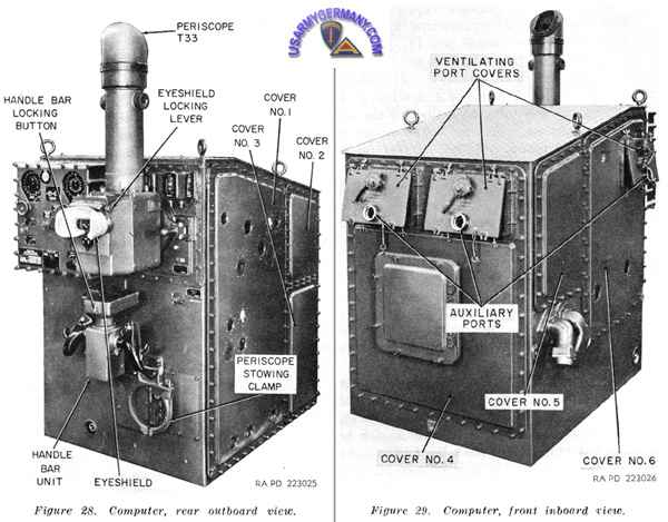 T27E2 Computer
|
| |
d. Computer T27E2. The components of the computer are contained in a large console mounted in the forward right corner of the gun carriage of the gun mount and to the right of the gun tube. One small unit, the wind resolver unit, associated with the computer is mounted on top of the elevation main case of the power control. A periscopic optical sight (periscope T33) is mounted on the upper area of the rear face of the computer console and, when traveling, this unit swings outward and down for protection of the mechanism and for lowering the overall silhouette of the weapon. In addition to the periscope, a dial panel unit containing the controls and dials incidental to computer operation and a retractable handle bar unit are also mounted on the rear face of the console. The handle bar unit, which is mounted below the periscope, provides a means of establishing computer synchronization with the target through the use of the periscope. Grasping either handle of the handle bar unit activates a deadman switch which transfers control of the gun azimuth and elevation data to the computer operator at anytime. After the power-control is energized a firing button and interlock trigger switch on either hand grip fires the gun. The dial panel unit, which is mounted to the left of the periscope, includes dials which display the azimuth and elevation of the computed gun position, and mounts secondary ballistic correction controls and indicators for air density, muzzle velocity, and trunnion tilt. The panel also supports a projectile time of flight indicator, a ready to fire signal light, and switches for changing the rate of scanner antenna nutation should tracking be not smooth, and for switching the gun from present to future position mode of operation and vice versa. In operation, the computer receives data from the radar relative to present slant range, azimuth, and elevation of the target. (Present elevation and present azimuth may also be supplied by periscope T33 or by target selector T1E2.) When the weapon is being controlled through the periscope, slant range may be supplied by the radar, or obtained in one of four ways: from automatic range in the radar, from manual range in the radar, from a value of estimated altitude set into the radar control panel, or from a value of "stored altitude" in the computer. The control switch for the "stored altitude" is on the radar control panel. Regardless of the manner in which input data are obtained, the computer supplies firing azimuth and quadrant elevation data to the power control, where these data are used by the power control equipment to position the gun accordingly.
e. Target Selector T1E2. The target selector (fig. 1) is an auxiliary sighting device which, during fire control system operation, is supported on its tripod and located at some convenient position within a 100-foot radius from the mount. The unit is used as tactical monitoring equipment by means of which the target selector operator continuously surveys the surrounding horizon and terrain for hazardous targets which the gun operators may not have observed. The target selector incorporates synchros which provide present coarse or approximate azimuth and elevation data relative to the selected target to the computer, providing the target selector switch at the computer is in ON position. Pressing a trigger switch on the hand grip of the target selector and with a push button on the communication junction box depressed, sounds a warning horn on the gun mount, directing the computer operator to cut in the target selector circuit and warning the gun crew that the weapon is about to slew.
f. Sighting System T34E1. For emergency ground fire only, gun laying may be achieved through the manual operation of the azimuth and elevation handwheels on the power control main cases. In these instances, the gun is sighted in the conventional manner with the telescopes of the sighting system. The sighting system consists of a supporting bracket mounted on the rear of the transmission box of the loader rammer and straddling the gun tube. The telescopes, one on the left for azimuth sighting (telescope T155) and the other on the right for elevation sighting (telescope T155E1), are mounted on the opposite ends of the supporting bracket. The telescopes and their mounting brackets can be detached from the main supporting bracket and stowed in a carrying case. Each telescope contains a suitable reticle which is illuminated by means of drycell batteries.
g. Wiring Set T5E2. The wiring set includes the junction box within the gun mount through which all off-mount equipment is electrically connected to the gun mount. In addition, the wiring set includes all on-mount cables which interconnect the various major items of the fire control system, plus the collector ring assembly through which are made all electrical connections between the fixed pedestal and the rotatable top carriage of the gun mount.
h. Cable System T31E1. The cable system includes the power cable through which all the primary electrical power is supplied from a power source to the weapon. The cable system also includes two cables which, through the communication junction box, interconnect the gun mount and the target selector. During travel, the two target selector cables are carried on a single reel, and the power cable is carried on a second reel. Both cable reels and the communication junction box are part of the system. The communication junction box is a means for connecting radio outputs and the telephones of the battery commander and the generating set operator to the communication system of the weapon. |
|
|
|
| T38 Integrated Fire Control Repair |
|
| |
| |
| |
| |
| |
|
|
| |
Related Links:
|
| |
| |
| |
|