If you do
NOT see the Table of Contents frame to the left of this page, then
Click here to open 'USArmyGermany'
frameset |
European Wideband Communications System
Defense Communications System
Looking for more information from military/civilian
personnel assigned to or associated with the U.S. Army
in Germany from 1945 to 1989. If you have any
stories or thoughts on the subject, please contact me . .
|
|
|
| Defense Communications System - 1970s |
|
| (Source: Hearings before a Subcommittee of the Committee on Appropriations, House of Representatives, Ninety-First Congress, Second Session, Part 3 - Operation and Maintenance (FY 1971), 1970) -- Lt Gen Richard P. Klocko, USAF, Director, DCA, testifying before the Subcommittee |
| PLANNING FOR THE DEFENSE COMMUNICATIONS SYSTEM |
The DCA (Defense Communications Agency) was established in May 1960 to bring together, in the interest of efficiency and economy, the long-haul communications of the military services into a Defense Communications System. Planning was initiated in 1960 to accomplish this and, for the long term, to develop the DCS to effectively, efficiently and economically meet the long-haul point-to-point telecommunications requirements of the DOD and of other Government agencies as directed.
In October 1961, the Secretary of Defense requested DCA to develop a long-range switching concept for the DCS. The DCA long-range switching concept for the DCS was prepared and forwarded to the Secretary of Defense in January 1962. Based on this concept, the Secretary of Defense approved the procurement of 14 analog switches in July 1962. The Air Force was assigned procurement responsibility subject to management direction from DCA. The military departments were assigned operating responsibilities for the switches and DCA was asked to furnish the military departments with locations, sizes, and estimated costs of the switches for which they were responsible. The development and implementation of the long-range switching concept for the DCS was the beginning of detailed subsystem planning by DCA. This type of planning for our major subsystems — voice, record, and transmission subsystems, including the Defense Satellite Communications System, is still going on.
Also beginning in 1961, a series of mid-range plans was produced. The purpose of the mid-range plans was to plan for the development and improvement of the DCS out to about 5 years in the future. The mid-range plans produced were:
 DCA mid-range plan — 1961 DCA mid-range plan — 1961
DCA mid-range plan — 1962
DCA mid-range plan for the DCS — 1966 (Published February 1964)
DCA mid-range plan for the DCS — 1967
(Published February 1965)
In addition to the mid-range plans just mentioned, DCA published a long-range plan in June 1964. This was entitled, "DCA 1976 Long Range Plan for the DCS." The purpose of this plan was to provide for an evolutionary development of the DCS during the 1973-76 time frame.
In October 1965, the Secretary of Defense in commenting on his review of the mid-range plan 1967 and long-range plan — 1976 stated that "In order to improve our planning posture, it is desired that DCA provide (1) a DCS plan covering the time frame from the date of submission to at least 10 years in the future, and (2) an annex to this plan covering in more detail the near term period."
DCA revised its planning accordingly. Three plans were published under the revised concept. These were:
Development plan for the DCS (1968-1978) (Published in February 1966)
Development plan for the DCS (1969-1979) (Published in October 1966)
Development plan for the DCS (1970-1980) (Published in August 1967)
These development plans were published in two volumes. Volume I was the basic plan and Volume II contained the near term improvement program, research and development, and resources summaries.
In September 1967, a revision of the DCA charter was published (DOD directive 5105.19) which states that the Director, DCA, is responsible for development of the DCS plan for submission to the Secretary of Defense through the Joint Chiefs of Staff. The DCS plan is defined as "a system plan, updated annually and
covering the time frame from date of submission to 10 years in the future — for the evolutionary development and improvement of the DCS in fulfilling communications needs of the DOD and other Govenrment agencies as directed.
Also in September 1967, action was initiated by the JCS which resulted in the present format of the DCS plan. The JCS guidance was forwarded to DCA in November 1967 and provides for the following:
(a) Development of the plan in five easily managed volumes —The initial guidance was modified somewhat to provide for six volumes. These are:
Volume I, Basic Planning Factors
Volume II, The Present DCS
Volume III, The Future DCS
Volume IV, Research and Development
Volume V Near-Term Development of the DCS
Volume VI, Synopsis
(b) Establishment of a planning cycle beginning in February and ending on August 1.
The DCS plan 1971-81 was produced over the period February 1968 through March 1969. As a result of OSD review of Volume I of the 1971-81 plan, an ad hoc working group was established by the Joint Chiefs of Staff to develop improved basic planning factors. The ad hoc working group has made a detailed study of the qualitative requirements of the users of the DCS for survivability, reliability, security, performance, and extension and reconstitution. The group devised means of assigning values to these qualities so that they can be treated realistically. The report of the working group is now being considered by the JCS who will forward it to the Secretary of Defense with comments and recommendations. We are beginning our planning cycle for the DCS plan 1973-83 this month. We will use the findings of the working group as a basis for development of the plan. The DCS plan 1974-84 will be based in a large measure on another study currently underway. This is the DCA future system studies program being carried out by
our system engineering facility which I discussed earlier.
It is a series of related system engineering studies, ranging in scope from retention of the present DCS with evolutionary improvements to a totally new all digital DCS. The studies are to determine the technical characteristics and design concepts which are economically and feasibly attainable for the DCS which will satisfy user requirements of the eighties. The study results will heavily influence the future design and performance of the DCS, the methods employed to transition to the future design, and the rate at which technological advances and near-term improvements are incorporated into the DCS. The initial technological definition of the future DCS which results from these studies will be refined and updated in future years through a continuing system engineering effort.
Our objective is to refine and improve the DCS plan from year to year so that it becomes truly a master plan for the DCS. It will be in phase with the DOD
planning, programing and budgeting system. It Will provide guidance for the preparation of supporting subsystem/project plans and supporting program and
budget documents necessary to achieve and maintain the necessary capability to accomplish the DCS mission. |
|
|
| (Source: TM 11-11-5895-1012-10, Operator's Manual, Technical Control Facility, Jan 1978) (Still under construction!!!) |
SYSTEM SERVICE INTERFACES AND TYPES OF SERVICE
2-7. Introduction
In this section system service interfaces and the types of service will be covered. In order for a technical controller to make the most efficient use of circuits and systems available, an understanding of the overall DCS and the facilities serviced is necessary. In addition to understanding the make-up of the DCS, the technical controller should be familiar with the transmission media used; communications facilities involved; the facilities which use the DCS mainline trunk routes as a transmission path; and the types of signals which are generated by these facilities. The information covered in this section is listed below together with appropriate paragraph references:
- DCS common user network
- Transmission media
- Communications facilities
- Relay centers
- Automatic Voice Network (AUTOVON)
- Automatic Digital Network (AUTODIN)
- Types of Signals
|
|
2-8. DCS Common User Network
a. A common user network is one that provides a set number of channels of voice or data communications for use by an even larger number of users on a shared basis. A user of a communications network can be a person making a telephone call; a communications center originating or receiving many teletype messages, data or facsimile signals; or a solitary teletypewriter maintaining contact with another like machine. The originating user can be linked to another activity within the same geographical area or in another geographical area. The point to remember is that the available channels of communications are shared by all or they are for “common usage.” Within the DCS the majority of the available channels are for common usage. Dedicated circuits, which make up the remaining channels, are established to support the traffic originating at dedicated facilities which provide communications of common interest, high volume, or priority traffic customers. The customers of these dedicated facilities can also be considered common users of the DCS, only with access to the system through a dedicated facility. The dedicated circuit ties two or more dedicated facilities, such as telephones, teletypewriters, data terminals, digital switches, etc., together and only those devices on either end of the dedicated circuit have the freedom of use of that circuit. All other users are blocked from access, even when the dedicated circuit is idle. |
|
| |
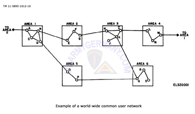 Figure 1: Example of world-wide common user network Figure 1: Example of world-wide common user network |
|
|
|
| b. Figure 1 is a representation of what a common user network looks like. Areas 1 through 6 represent widely separated geographical areas of the world. Locations A through S represent communication facility stations within those areas. The communication facility stations can be a tributary station, or a minor or major relay station. Stations within a geographical area provide the means for one user within that geographical to communicate with any other user within the same area. Interconnecting links between geographical areas, such as between stations B and E, D and O, or A and M allow users within Area 1 to communicate with users within Areas 2, 5 and 4 respectively, and vice versa. Interconnecting links between Areas 2 and 3, 3 and 4, 3 and 6, and 5 and 6 extend communication lines for all users within one geographical area to communicate with all users within any other geographical areas. A world wide network is now established. |
|
2-9. Transmission Links and Media
a. Modern long-haul communications is accomplished by multiplexing many channels of communications simultaneously over the same transmission link. A transmission link, is a communications path between two stations which have a breakout capability to provide users with access to the system. In Figure 1 a transmission link would be the path between Stations A and B, D and O, P and Q, etc. Different transmission media is selected to provide the means for traffic to move over the distance between the stations. The different types of transmission media include:
(1) High Frequency Radio. This media can cover distances up to 6,000 miles. The ground distance between stations is dependent upon the equipment selected and station design. A limitation on high frequency radio is the small number of multiplexed channels which can be carried, usually 4 voice frequency channels.
(2) Line of Sight Radio. These radio links operate in the very high frequency, ultra high frequency or microwave frequency regions. There must be a line-of-sight path between the transmitting and receiving stations, however, this limitation is overshadowed by the capability of such links carrying a high density of multiplexed communications channels.
(3) Tropospheric Scatter Radio. This type of media relies on the forward scatter technique or propagation. Tropospheric scatter can cover distances between 100 to 500 miles and carry a large number of multiplexed channels, depending upon system design. This media of transmission is also referred to as over-the-horizon propagation and does not require a line-of-sight path between stations.
(4) Satellite Radio. The distances covered by this media depends upon how high above the earth the satellite relay station is positioned. The distance between earth stations usually vary between 2,000 and 6,000 miles. The transmission link is capable of carrying many multiplexed channels, The main limitation is that the channel capacity and position of the satellite relay station cannot be upgraded or changed.
(5) Metallic Links. Metallic links can be coaxial cable, paired cable, or open wire. A metallic link can be of all one type or by use of interfacing equipment be a mixture of two or all three of the types. A metallic cable link can be either submarine or landline. Metallic systems can carry a low density or a high density of multiplexed channels depending on the equipment and the type of cable selected and user requirements. The major limitation is in the construction of such systems. Right-of-way must be arranged and cable or wire laid to make the physical connection between the two breakout points. An added factor is the maintenance, and when needed, the repair of the outside plant facilities.
b. Transmission links utilizing line-of-sight paths, tropospheric scatter, and metallic media can cover the required distance between breakout points directly or may require intermediate stations to span the distance between the two stations providing the breakout capability. These intermediate facilities are called relay stations for radio systems and repeater stations for metallic systems. In either case the relay or repeater station performs the same function. It will equalize and simplify the incoming signals to permit the re-transmission of a signal that, as near as possible, duplicates the original transmitted signal.
c. Referring to Figure 1, the common user net work depicted can be made up of all the types of transmission media described above. In addition, any one or all of the transmission links shown could have one or more intermediate relay or repeater stations as part of the link, or span the distance without the need of these stations. The type of equipment selected and the make up of the transmission link is determined by the distance between breakout points, strategic and economic factors, and the technical parameters required to provide the appropriate type and grade of service to the users. |
|
Communications Facilities on the DCS
2-10. Communications Facilities
The communications facilities, which when connected together to form the worldwide common user system can be classified as tributary stations, major relay stations, or minor relay stations.
|
| |
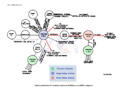 Figure 2: Interconnection of communications facilities Figure 2: Interconnection of communications facilities |
|
|
|
a. Tributary Stations. A tributary station provides communications services, telephone, teletype, data etc., to activities located at the same base or installation. It is not a requirement that tributary stations be located on a base or installation. It could be positioned in a civilian community where there is a concentration of DCS users. The equipment installed at the tributary station is compatible to that of the relay station or message switching center that provides access to the DCS. In Figure 2 the facilities located at Camp P and Camp J, are tributary stations located on the installation. From the tributary station, lines extend outward to the user equipment. This equipment can be a single teletypewriter; banks of teletypewriters located in the installation communications center; data terminals; a computer; a facsimile machine; and the installation telephone exchange. The telephone exchange further extends the service of the tributary station to each authorized telephone user on the installation. Stations PDQ and LMN are tributary stations not located on an installation, but in a town or city in which there are a number of authorized users requiring access to the DCS. The transmission link between the tributary station and its associated access station to the DCS can be direct or require the use of repeater or a relay station.
b. Major and Minor Relay Station Tributary station access to the DCS is through a relay station, Traffic flows through the access relay station onto the system to the distant tributary station. Relay stations are classified as major or minor depending upon their position in the DCS.
(1) Major Relay Station. In Figure 2 DCS Station ABC can be classified as a major relay station. It is situated at a nodal (or junction) point of two or more DCS subsystems. In addition to passing traffic originating at or destined for a connected tributary station, it also acts as a circuit switching station. The station is located at the junction of Government owned Systems #1, #2, and #3 of the world-wide network, and is also an access point to leased circuits carried over a commercial facility, and a Government owned satellite system. Signals entering ABC on System #3, as an example, from tributary station LMN or beyond DCS Station XYZ, and not destined for a connected tributary station, would be switched to leave the nodal point on Government System #1 or #2, the commercial facility, or the Government satellite system. The switching can be accomplished on a channel, group or supergroup level. DCS Station ABC provides many routing capabilities for signals originating at an associated tributary station, including interconnection of users located at any of the serviced tributary stations.
(2) Minor Relay Station. DCS Station XYZ Figure 2 can be classified as a minor relay station. The amount of installed equipment would be much less than that of DCS Station ABC since it is not at a nodal point. It services only one tributary station, and provides access only to the East or West on System #3. |
| |
| |
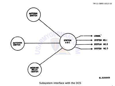 Figure 3: Subsystem Interface Figure 3: Subsystem Interface |
|
|
|
2-11. Message Relay Center Interface
It is not feasible (economically or practically) to have each teletypewriter user connected directly to every other users machine. Economic interconnection is established through a complex subsystem network of message relay centers. The worldwide DCS is used as the vehicle to transmit messages from one user to another. Individual teletypewriter signals are multiplexed into composite signals which are then transmitted over the DCS system voice channels. So that every teletypewriter user can transmit to any other user, a system of message relay centers has been established to switch (or relay) the messages from one system to another and move it from the originator to the addressee as quickly as possible. The message relay center may be an activity serviced by a tributary station or a tributary station itself. Message relay centers are classified into three categories: manual, semiautomatic, and automatic.
a Manual and Semi-automatic Message Relay Centers. The manual and semiautomatic message relay centers employ the torn tape method of operation. An operator tears the incoming message tape off of a receiving machine, reads the routing indicator, and hand carries it to the transmitting position. This is a relatively slow method since the speed of passing a message tape through the office is dependent upon the speed and accuracy of the operator in reading the routing indicator, carrying it to the transmitting position, and preparing it for retransmission. The semiautomatic message relay center speeds up the retransmis sion process by having an automatic numbering process and tandem transmitter distributors with automatic switching between them.
b. Automatic Message Relay Centers. There is no need for operator intervention during normal operation of this type of message relay center. Messages am automatically passed, via cross office equipment from the receiving machine to the transmitting position, renumbered and retransmitted to the next relay center or to the addressee. This permits rapid relay of messages through the relay center. Delay is only dependent upon the speed at which the cross-office equipment operates. So that this facility can operate at maximum speed and efficiency, there is a need to maintain precise accuracy in the production of the original message tape, and high quality of the DCS circuits over which the message travels. |
|
2-12. AUTOVON Interface
a. The worldwide DCS main-line trunk routes provide the transmission path for voice frequency communications over the Automatic Voice Network (AUTOVON) another DCS subsystem. The basic objective of AUTOVON is to establish a common-user automatic switching network that provides worldwide compatibility, reliability, flexibility, and greater survivability of telephone communications. The voice communications capability is provided between Department of Defense users and between Department of Defense users and certain non-DoD users. The system is established primarily for voice communications, but it is capable of handling graphic and data transmissions on a user-to-user basis. It is capable of handling secure communications when the appropriate equipment is installed at user locations. For operational and control purposes, the AUTOVON switch has a built-in TCF which functions as a tributary station to a DCS major or minor relay station.
b. The Automatic Voice Network is intended to offer identical services worldwide to its users. Services that are available to users system wide are as follows:
(1) Normal Service. It provides the capability for direct dialing from one user to another on a worldwide basis. In instances where limited trunking facilities are available, the user will place the call through a local operator or a Dial Service Assistant.
(2) Four-Wire Service. Selected subscribers to AUTOVON are provided with a special I-wire telephone for direct access to the network. Data subscribers are provided access to specially conditioned AUTOVON data circuits. The signaling from a 4-wire instrument is dual-tone, multi-frequency. The four-wire service subscribers can also be provided with up to three levels of precedence for pre-emption of lower level precedence calls when necessary.
(3) Off-Hook Service. The off-hook service subscriber is immediately connected through to a pre-designated subscriber as soon as the handset is lifted from the cradle.
(4) Special Networks. These special networks may allow complete privacy to specially designated users or allow them access to the entire AUTOVON network. These special networks fall into two categories:
(a) Category 1 allows subscribers to use abbreviated dialing with pre-emption capability.
(b) Category 2 provides special treatment to users within a special interest community. This community of special interest can be within one geographical area or worldwide. General purpose subscribers can be prevented from calling into category 2 networks network for the transmission and category 2 subscribers can be denied access to the general purpose network.
c. Normally connection through the AUTOVON from user to user will be completed in about 4 seconds. Difficult connections may take up to 10 seconds through unusual or complex routing. This is switching time only and excludes the time required to dial. Off-hook service connections are normally established in less than 2 seconds. So that designed speed and quality of service can be realized, AUTOVON designated DCS circuits must be maintained at a high quality. |
| |
| |
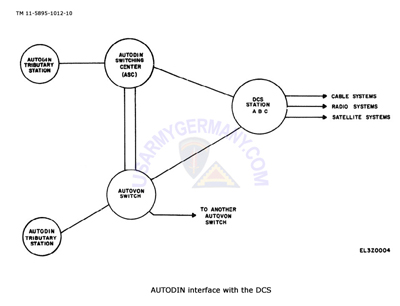 Figure 4: AUTODIN Interface Figure 4: AUTODIN Interface |
|
|
| |
2-13 AUTODIN Interface
a. Another communications subsystem interface which a technical controller must be aware of and familiar with is the Automatic Digital Network, (AUTODIN). AUTODIN inter-station trunks are supplied by the worldwide DCS main-line trunk routes. The transmission quality on the AUTODIN trunks is the responsibility of the DCS Station Technical Control Facility. The technical control personnel monitor all incoming dc circuits and breakdown voice frequency telegraph carrier into individual dc circuits. These circuits are then extended to the AUTODIN switch. Like the AUTOVON, the AUTODIN Switching Center has a built-in Technical Control Facility for operational and control purposes.
b. AUTODIN Is a store and forward switching network for the transmission of digital data. The AUTODIN is a high speed, flexible, computer controlled network which provides the Department of Defense and other Government agencies with digital communications. The flexibility of AUTODIN is illustrated by the following capabilities:
(1) Processes traffic on a store and forward basis between two widely separated users.
(2) Sends and receives traffic to and from users at transmission rates between 75 and 2400 baud and between AUTODIN switching centers at rates up to (4800) baud.
(3) Accepts traffic from teletypewriter, punched card terminals, magnetic tape terminals, and computers.
(4) Exchanges traffic between users whose equipment operates at different speeds and use different codes and formats.
c. The AUTODIN interface with a DCS Station is illustrated in Figure 4. AUTODIN tributary stations are connected to the AUTODIN Switching Center (ASC) directly or via AUTODIN conditioned trunks of the Automatic Voice Network (AUTOVON). The ASC is connected for transmission to another ASC via the DCS Station which acts as the gateway to the DCS. The traffic is cleared through the station and routed out on predetermined and preconditioned circuits over cable, radio, or satellite systems. These circuits can be over Government owned facilities or over leased facilities.
d. The AUTODIN Switching Center can be connected to another ASC over the AUTOVON as a primary route or, in the event of a failure of a primary route, as a backup circuit through the establishment of on-call patches. In addition, users of AUTODIN who do not require full time access to the ASC can be connected to the switching center over AUTOVON on a call-up basis. In cases where AUTODIN is routed over AUTOVON for restoral or for non-full period users of the AUTODIN to gain access to the ASC, it is the responsibility of the technical controller at the ASC to establish the path. The controller dials up the distant ASC or user, establishes voice contact, makes the required equipment connections to the circuit, and then turns the circuit over for digital communications. After restoral of normal routing or at the end of the user real-time schedule, the originating technical controller coordinates the release of the called-up circuit. |
 |
|
|
| (Source: AFM 100-32(C2), via Bill Richey) |
Route Maps
European Broadband |
|
|
|
|
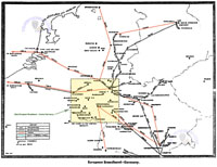
1. Germany, 1967 (341 KB)
|
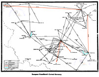
2. Central Germany, 1967 (295 KB) |
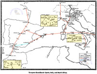
3. Spain-Italy-N. Africa, 1967 (341 KB) |
|
|
|
|
| FELDBERG (TAUNUS) |
|
| IMAGE: 1 |
|
| (Source: Email from Don Engel, Det 12, 1945th Comm Gp) |
|
I was stationed at the Air Force Feldberg site (Det 12, 1945th CG) in the Taunus just north of Frankfurt, from Jan 1966 to Jul 1969, and again from Jan 1973 to Jul 1978. On the picture of the German Grosser Feldberg you asked if anyone knew whether the Air Force ever used that German tower, and to the best of my knowledge, we never did. (It is part of the German telephone system.)
The Air Force tower you show was built between 1960 and 1963. Previously the site was used by the 603rd AC&W for a missile site.
There were several land lines between the Air Force Feldberg, and the German Grosser Feldberg that went on into the States via marine cable for the AUTOVON system.
When the U.S. provided NATO with a demonstration of AWACS in 1978, the down leg shot went from the AWACS aircraft to an Army communications truck sitting next to the German Grosser Feldberg. A pair of twisted cable pair ran from the truck to the German tower, and then on to the Air Force Feldberg for relay into NATO Headquarters. During the demonstration we lost contact with the Army truck, and I was allowed into the German tower to track down the problem. It turned out that someone had drug a sled over the twisted cable pair between the truck and the German tower cutting it in half. I made a quick connection, and the demonstration was back on line.
Don |
|
|
|
| Radio Equipment In Use 1960s-70s |
|
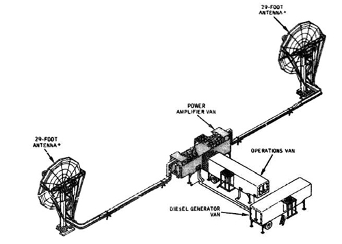 |
| AN/MRC-85 |
| |
(1) AN/GRC-66 Tropo Scatter equipment
(2) AN/MRC-85 Tropo Scatter Terminal; MRC-85 consisted of three ten-ton semi-trailers, one each for a radio, a multiplexer and two 150-kilowatt generators; 29-foot antenna used with MCR-85; 60-foot antenna with MRC-85A
3) AN/MRC-95 HF Transceiver equipment
|
|
|
|
|
|
|
| |
|
| |
|
| |
|
| |
|
| |
|
| |
|